BAIDU_CLB_fillSlot("890672");
newspaper After the rapid growth of printing at the beginning of this century, the total amount of newspaper printing has declined year by year in recent years. Various newspapers and media have been seeking changes in the decline, such as through the control and change of the number of pages, content and even the print layout, in order to stabilize Circulation and economic benefits. Under the influence of the industry's development trend, the printing presses of major newspapers across the country have rarely introduced new imported newspaper rotary presses in the past five years, and the high-speed newspaper rotary presses that were previously introduced in line with the structure and quantity of printed products at the time were in the face. When it comes to the ever-changing needs of newspaper printing, its structural and functional configuration often becomes the constraint of today's newspaper printing. If a wide-format newspaper press that satisfies a large print volume restricts its response to paper width changes, a double-sided color press without an ink path clutch restricts the printing of single-sided color or black-and-white newspapers, and the wide-format newspaper printing mechanism It is printed on the 24th edition of the newspaper (can be printed but not economical, green).
In order to adapt to the changing needs of newspaper printing, several major equipment suppliers have proposed relevant technical transformation proposals and programs in recent years, but the price is not cheap. Based on its actual use, our company has independently carried out technical transformation on the ink road clutch mechanism of Manroland UNISET78 high-speed rotary newspaper printing machine. After the transformation, it not only facilitates production, improves work efficiency, but also saves a lot of equipment transformation costs. Here, the specific transformation methods and processes will be briefly explained, and criticisms are welcome.
Reason for technical change
In 2008, our company purchased the Manroland UNISET78 high-speed rotary newspaper printing machine. The equipment is equipped with 6 printing towers, 3 folding machines and 8 paper holders. One of the printing towers is a semi- commercial printing tower. At the time of purchase, considering the cost factor and the characteristics of the printed products, each printing tower was equipped with an ink path clutch device only in the 2nd, 4th, and 6th color groups (see Figure 1), which made it possible to satisfy 4+4, 4 +1 newspaper printing. The 2, 4, and 6 color ink paths can be automatically disengaged when 4+1 newspaper printing is performed, so it is very convenient to switch between 4+4 and 4+1 product printing. However, with the changes in product structure and publishing methods, some printing towers will have 3+4, 1+4 or 1+1 printing methods when printing in version 16 or 24, and due to numbers 1, 3 and 5 The color group does not have a clutch roller clutch mechanism, which causes inconvenience to the production conversion of the product. We can only remove the ink set ink path without printing by removing the transfer roller, and install the white plate on the plate cylinder at the same time, but this can only solve the problem that the color group is not inked, correspondingly The rubber roller will still idling, which will easily cause the rubber roller to wear and wear. In order to solve this problem, improve the adaptability of the printing mode of the printing press, and avoid the wear of the entire ink path due to idling. We designed and installed a manual squeezing roller clutch mechanism, which can be used to disengage the entire ink path during production. Stop and do not need to install the white plate on the plate cylinder. This not only saves printing preparation time, but also effectively reduces the printing cost and reduces the wear of the rubber roller.
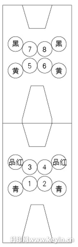
Figure 1 Schematic diagram of a printing tower of the UNISET78 high-speed rotary newspaper printing machine
Technical reform program
In order to prevent the two sets of the squeezing rollers from rotating during the printing process, we selected the gears that the two sets of squeezing rollers co-mesh (and this gear is the excessive gear of the power input) as the clutch gear. We have changed the way the previous over-gears were fixed so that the gears can slide in the axial direction as needed, eventually reaching the clutch transfer roller (see Figure 2).
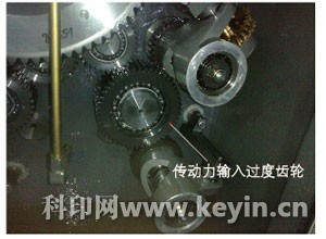
Figure 2 UNISET78 printing unit ink lining mechanism
When choosing the way to implement the organization, we have two options: pneumatic and manual, both of which have advantages and disadvantages. The advantage of pneumatics is that the execution is quick and accurate; the disadvantage is that the electrical control part of the pneumatic components cannot be integrated into the original control system of the printing machine (the computer program of the control part must be modified by the manufacturer), so that the clutch mechanism detection control is complicated and the mechanism safety is low. . The advantage of manual is that the safety is high and the system works reliably; the disadvantage is that the manual clutch takes a little longer. Considering that the organization is working in a high-speed rotating environment, the safety of the organization should be ranked first, and finally we chose the manual clutch solution.
Program implementation
First, we designed a support shaft. One end of the shaft is fixedly mounted on the original mounting hole on the inner side of the wall panel. The fixing method is the same as before. The other end is used to install the clutch sleeve. The tolerance between the support shaft and the clutch sleeve is 45H5/f4, this kind of cooperation can ensure that the radial runout of the gear above the sleeve is within a certain range, does not affect the transmission accuracy, and can make the gear move freely when it is clutched.
A groove of 12 mm wide, 3 mm deep and 100 mm long is milled on the mating surface of the support shaft and the clutch sleeve for storing the lubricating oil flowing down from the upper spray to lubricate the mating surface between the clutch sleeve and the support shaft. To ensure that the clutch is free.
Secondly, we designed a clutch sleeve, which is fixed on the outer side of the clutch sleeve by bearings. The clutch sleeve is mounted on the support shaft for axial movement. The axial movement distance is 68mm. This size can make the excessive gear and the upper level. The gears are completely separated, and there is a gap of 6.5 mm between the two gears, which can be separated from the next gear, and the length of the engaging surface is 8 mm.
On the side of the clutch sleeve we machined 3 threaded holes for fixing the guide plates. The purpose of the guide plate is to prevent the movement of the clutch sleeve in the circumferential direction, and to carry the axial movement along the guide rod under the action of the clutch rod; the second is to fix the manual clutch rod (see Fig. 3).
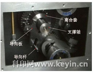
Figure 3 UNISET78 printing unit ink lining mechanism increases the effect of the rear panel of the clutch device
Finally, we designed and installed a set of cross-frames on the outside of the gearbox cover. In one case, it can support the manual pull rod; second, it can limit the position of the gear.
The horizontal frame is positioned with the centerline reference of the fixed threaded holes on both sides of the original gearbox cover, and the holes are machined in the corresponding positions for the support of the tie rod. When processing the set of cross-frames, we require The machining of the mounting hole is completed at one time with the center position of the rod hole as the reference point, and the dimensional error does not exceed 0.05 mm. A rotatable limit plate is designed to be mounted on the horizontal plate in the corresponding groove on the tie rod to limit the axial position (off-and-close position) of the clutch gear. The position of the excess gears at different positions of the printing unit is also different. In this case, we designed two sizes of cross-frames.
The appearance of the whole device after the completion of the transformation is shown in Figure 4, and the final assembly diagram is shown in Figure 5.
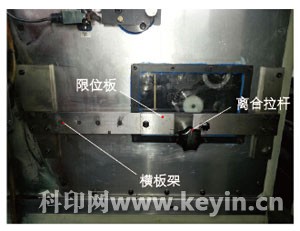
Figure 4 is an external view of the printing unit after adding the manual clutch mechanism of the ink roller
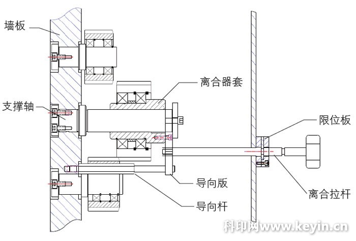
Figure 5 Overall assembly diagram of the entire device
Case evaluation
The entire technical transformation completed a total of 10 sets of clutch mechanism transformation, each set cost 8,000 yuan, a total of 80,000 yuan. Saved more than 500,000 yuan for the unit (such as the factory transformation to about 600,000 yuan). Through the transformation of the UNISET78 machine squeezing roller clutch mechanism, not only the printing machine can quickly change the printing of different color registration requirements, which brings convenience to the printing work, improves the publishing time of the newspaper, improves the work efficiency, and effectively Reduces wear on the machine rubber roller and anilox roller, saving printing costs. Calculated according to the daily printing tasks of the current equipment, 1500 sheets of plates are saved each year, and the cost is about 30,000 yuan.
HAIPENGDA Plastic Toys Co., Ltd. , https://www.hpdtoys.com